Power Circuit
|


|
||||||||||||||||||||||||||||||||||||||||||
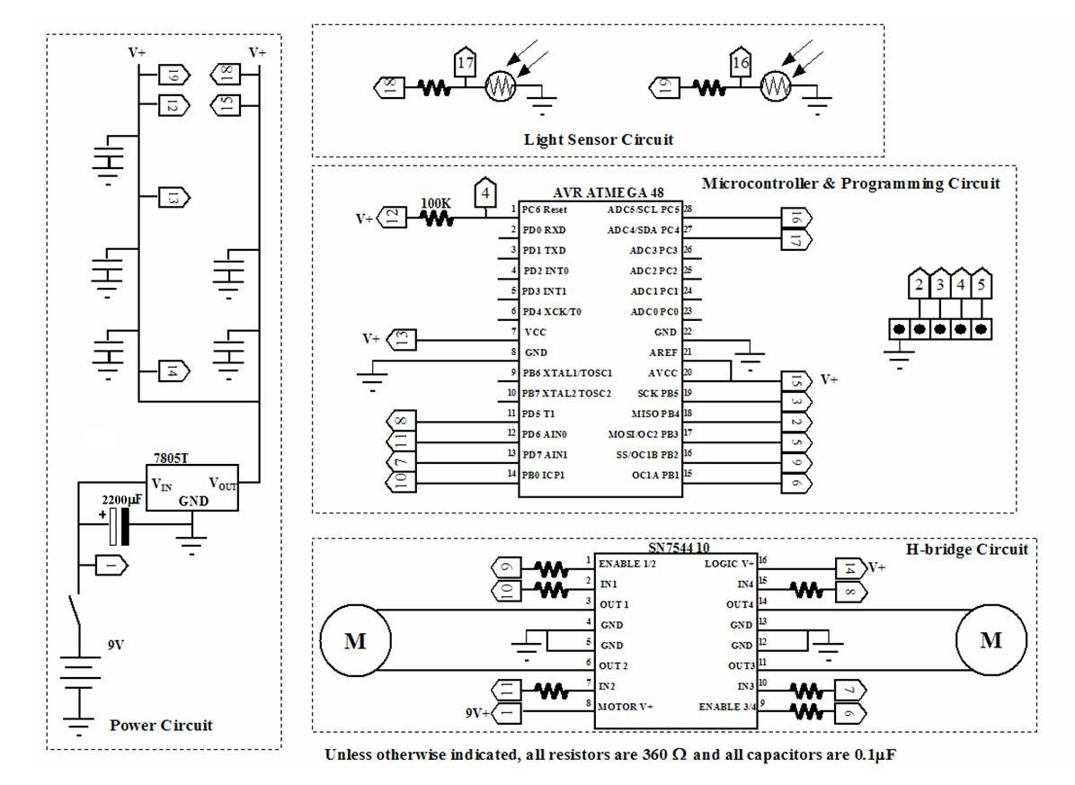
Figure 23: Power Circuit |
Microcontroller and Programming Circuit
This circuit contains the microcontroller and the wires that connect microcontroller to the sockets where the programming cable is connected to the breadboard. The programming cable will be plugged into H46 through H50. It is a good idea to take a marker and mark these socket holes. The programming cable is plugged in with the ground wire in socket H46. Mark H46 with a different color than the other sockets. This will make it easier to remember which way to plug the cable into the socket. Figure 24 list what goes where.
|
|||||||||||||||||||||||||||||||||||||||
Figure 24: Controller Circuit |
H-bridge Circuit
This is the circuit that allows the microcontroller to run the motors. The microcontroller is protected from noise feedback from the motors by the resistors on each of the control lines. Note that you need to add either pieces of shrink tubing or pieces of insulation that you stripped from wires to the leads of the resistors so that the resistors do not short out against each other. Also note that you have an even chance of wiring each motor up backwards. That's OK. You will be able to tell if this has happened when you run the demo program. If the motor is wired wrong, just switch the location where its two wires are connected. Figure 25 lists the items and where they go. Please note that the bent parts of the leads on some of the resistors have to be different lengths so that the resistors can clear each other when you assemble the circuit.
|
||||||||||||||||||||||||||||||||||||||||||||||||
Figure 25: H-Bridge Circuit |
Light Sensors' Circuit
Up to now, you have just built a platform. To make a true robot, it has to be able to sense something in its environment and change its actions based on what it senses. The CDS cells in this circuit will sense light intensity in two directions. Install the components shown in Figure 26. When you install the sensors, twist them so that the one on the left side of the bot points forward and slightly to the left and the one on the right side points forward and slightly to the right (Refer to Figure 21). The sensors are connected to analog to digital (A/D) inputs on the microcontroller. This will allow the microcontroller to measure light intensity to the right and left of the bot. With this information, the program can be configured to cause the bot to either turn toward or away from a light source.
|
|||||||||||||||||||||||||||
Figure 26: Light Sensor Circuit |
Programming
Now that you have the CIRC Bot and its programming cable built, it is time to test it. Make a directory on your PC where you are going to save programs for your CIRC Bot. Go to the SERVO website or Click Here to download the program "CIRC_bot_shell.bas" that goes with this article to the directory you just made.
Install BASCOM AVR on your PC following the instructions at the MCS website. Start the program and click on "Options" on the toolbar. In the dropdown box that opens, pick programmer. This will cause a popup box to open where you can select the type of programmer you have. Select "Sample Electronics programmer" and click OK.
Click on the folder icon in BASCOM. This will open a popup window where you can choose a file to open. Browse to the folder you created and pick "CIRC_bot_shell.bas". A popup window will open showing you the program listing. You will need to compile the program by clicking Program on the toolbar and then compile in the options (or just hit the "F7" function key).
Once the program is compiled, it needs to be transferred into the CIRC Bot. Install four AA batteries into the bot. Take some small blocks and put them under the bot so that the wheels don't touch the table. Attach your programming cable to your PC and to the bot. Remember to put the connector in correct direction (that is why you made the socket hole for the ground wire a different color). Now turn the bot on.
In BASCOM, click Program on the toolbar and then send to chip (or hit "F4'). The programmer window will come up and identify the correct chip, however, it might not actually download the program to the bot. In the programmer window, hit the erase chip button, then the program button, and finally the compare chip to buffer button. If the programmer responds Ok, you have just programmed your robot! Switch the robot off, unhook the programming cable and set the bot on a floor. Now turn the switch back on and see what your bot can do!
The program you loaded is broken up into sections and is commented fairly well so I won't go into much detail about it here. Use the help guide and the BASCOM manual to learn what the individual commands do.
The program is initially set up to run a blind demo. In this demo mode, the bot will go through a series of motions:
Turn in place left
Turn in place right
Go forward
Go backward
Go forward & right
Go forward & left
If the bot moves, but does not do these motions in this order, one or both of your motors are connected backward. Simply switch around motor wires and try again.
By changing out some comment marks (') where indicated in the program, you can switch from the blind demo to a turning in place light sensor demo. Notice that the robot does not weathervane directly to the brightest source of light. This is because the two CDS cells are not exactly matched (unless you are incredibly lucky). You could measure each CDS circuit using your multimeter under the same lighting conditions and add a variable resistor to tune the two circuits to match. You could also wait until next month when we add an LCD display and use that to find out what values the two sensors put out under the same conditions. A final option would be trying adding various offset values to the formula in the program that compares the output from the CDS cells, recompiling and running the program with each change and see what happens.
Troubleshooting
Just like last month, there is a possibility that things did not go right. Your robot may either just sit there or one of the motors runs while the other does not turn at all. Worse yet, the programmer may say that the microcontroller is not found and you can not download the program. If any of these things happen, consider yourself lucky. You get to apply the troubleshooting tips described in last month's article to your CIRC Bot.
If a motor refuses to turn, pull its leads from their regular positions and connect them directly to the V+ and GND rails and turn on the power switch. If the motor now turns, the problem is in the connections to the H-bridge. Turn the power off and put the wires back into the correct place and check that all the connections in the H-bridge circuit match what is in the table. If they match the table, look for short circuits between various lines from the microcontroller to the H-bridge chip. Use your multimeter to read resistance between each microcontroller pin that is wired to the H-bridge and all of the pins on the H-bridge chip (with the robot's power turned off). You should only get a reading on one pin of the H-bridge chip. If you get readings on two pins, you have a short. Look at the wires and especially the resistor leads for the two lines that are shorted. Somewhere there is metal touching metal. If you can not find a short, completely reverse the connections for the left and right motors of the H-bridge; both where the motors are connected and where the signals are connected form the microcontroller. 99% of the time, you will find the problem in one of these steps. It is extremely rare that a new motor control chip is fried, but if all else fails, replace the chip.
If you are getting an error while trying to program the microcontroller, start by looking at your programming cable using your multimeter just like you checked your circuits last month. If all the lines are correct (no short circuits, no open circuits, all the ground pins are connected together), your next step is to check the wiring on you bot. Are all of the wires listed in the microcontroller and programming circuit table run between the correct locations? Is the pull up resistor connected between the right pin and V+ ? Are all of the ground lines connected to the correct pins and to GND rails instead of V+ rails? Is the chip in the correct way? Did you have your programming cable plugged in the right way?
If the bot only turns in one direction when you modify the program to do the light sensor test, you should first try removing the CDS cell on the side toward which the bot is turning. The bot should now turn in the opposite direction. Putting the CDS cell back in place should cause it to go back to turning the original direction. Swapping the two cells should cause the direction to reverse. If this happens, there is not a problem; it is just that your cells are nowhere near matched.
If one of those steps is unsuccessful, the problem is in your circuit. Compare all the connections to the build table and trace them using the multimeter.
Variations
The whole point of the CIRC Bot is to learn how to work with the basic components that go into most robots. Up to now, you have been merely following assembly instructions. Now it is time to strike out on your own. Fortunately, it is not uncharted territory. Many nice people have taken the time to explain things that they know about robotics on web sites that you can easily find with Google. Here are some suggestions to get you started:
Better H Bridge Configurations
The H-bridge design I showed you on this robot is fairly common, but it has one drawback, the robot looses torque as it goes slower. This means that below some speed, it will not be able to overcome its own static friction to begin moving. By changing the way the H-bridge is connected to the microcontroller and modifying the program, you can make a locked-antiphase PWM control. To figure out how to do this, start at http://www.barello.net/Papers/h-bridge.pdf where Larry Barello explains what H-bridges are, how PWM works, and how to configure different types of motor control. To figure out how to change the program, go to the BASCOM AVR forums on the MCS Electroincs website http://www.mcselec.com/index2.php?option=com_forum&Itemid=59 and look through past postings.
Fun with CDS Cells
CDS cells are resistors whose resistance values vary with the amount of light. The build instructions had you make two voltage dividers each utilizing a CDS cell and a regular resistor connected in series between V+ and GND. Each of the analog to digital converter inputs read the voltage value between a CDS cell and a regular resistor. This required two A/D converters on the microcontroller. You could make a single voltage divider utilizing both CDS cells (and probably at least one other resistor to balance the circuit) that would tell you which cell was exposed to a brighter light. Such a setup would require only one A/D converter on the microcontroller.
You can also read the cells using a regular digital input instead of an A/D converter. Remember that while we normally consider 0 volts to be a digital 0 and 5 volts to be a digital 1, there is actually a wide band of voltage that the microcontroller will accept for each. Find out what those ranges are and how to tune your voltage divider using a variable resistor (trimmer pot) so that a brighter light on one side would produce a voltage in the digital 0 range and brighter light on the other will produce a voltage in the digital 1 range.
The voltage where the change occurs is at a slightly different value in each chip manufactured. Your sensors will pick up electrical noise. This will cause their output to vary slightly even in constant lighting. When you are near the switch over voltage, this noise will cause the digital signal to flip back and forth between 1 and 0. There are several ways to remove this undesirable characteristic. One way uses what is called a Schmitt trigger.
All of the examples so far have had the bot switching between turning left and turning right. You really want a third option where the bot goes straight ahead unless the difference in lighting between the two cells is above a certain threshold. There are many ways to do this in both software and hardware.
Finally, you can also make a simple line follower by bending the CDS cell leads so that the cells point downward and adding a light to the front of the bot.
Conclusion
When you finish the work described in this month's article and online supplement, you can honestly say that you built a robot. Next month we will greatly enhance your robot's sensor suite and we will add a LCD display so your bot can tell you what it is thinking. Until then, have fun with your project!