CIRCBot
Tools & Soldering
Introduction to the Online Project
This project accompanies part 1 of Servo magazine
series Beginner's Robotics on $50 a Month.
In the magazine article, you learned about the basic tools that
every robot hobbyist should have. You
also learned some basic tips on how to find the best prices for tools and
parts both online and locally. Now,
you will learn one of the fundamental skills that every robotic hobbyist
should know, soldering
Soldering
There
are many sites on the net that tell you how to solder.
One of the best sets of instructions is the N0SS solder notes at
Elecraft: http://www.elecraft.com/TechNotes/N0SS_SolderNotes/N0SS_SolderNotesV6.pdf
. There are also short how to
solder training videos on the web at: http://radiojove.gsfc.nasa.gov/elab/soldering.htm.
The
N0SS instructions and the radiojove videos are very good. Here are few
extra tips to make things easier for the beginner:
A
well cleaned soldering iron tip is important.
On cheap irons, the tips are coated with oil for shipping.
This oil needs to be burned off before the first time the iron is
used. In addition, the plating
used on the cheap irons does not "wet" easily.
That means solder will not easily spread over the tip.
When you first get your iron, plug it in and set it in a place
where it will not be bumped. Allow
the iron to heat up for several minutes.
You will probably see a little bit of smoke come off the tip.
This is the oil burning off. Once
the smoke stops, unplug the iron and let it cool.
Once it is cool, take fine sandpaper and sand the plating off of
the tip. Don't worry, it is
just a $5 iron. The copper
below the plating will wet better.
Now
the tip needs to be tinned. There
are tinning compounds available, but you can also use regular solder.
Get your sponge wet and squeeze most of the water out of it.
Heat up your iron and touch the tip of the solder wire to the tip
of the iron. When a small
amount of the solder liquefies and begins to bead on the tip, pull the
solder wire away and wipe the tip of the iron on the wet sponge.
Most, but not all of the solder will come off the tip.
Repeat this several times until there is a fairly even silver color
to the tip. Unplug the iron
and let it cool. When it is
cool, lightly sand the tip again. This
time, do not sand it so much that you remove the coating you just put on
it.
Now
you are ready to learn the biggest secret in soldering: rosin paste. This
stuff is available from Radio Shack, All Electronics, DigiKey, and Wright
Hobbies. Apply the paste only to the areas where you want the solder to
flow - use the point of a toothpick - and only apply enough to give a
slightly oily look to the area - no lumps. Rosin paste is the biggest aid
to beginner's I have seen. I wish some one had told me about this when I
first started.
Each
time you use the soldering iron, the tip of the iron needs to be re-wetted
with a tiny amount of solder. I guarantee you will use too much solder at
first when wetting the tip. This is ok since it will allow you to do the
one hand soldering method that my wife, Kate, came up with: Apply rosin
paste to the joint to be soldered. Clean the hot iron tip with the wet
sponge. Apply a small bit of solder to the tip. When there is a small bead
of solder on the tip, touch the tip to the joint. Hold the tip to the
joint until the bead of solder spreads across all of the area where you
applied rosin paste (1-2 sec). Repeat all steps for the next joint. When
you are finished for the day, use a Q-tip and alcohol to clean any excess
rosin (there should be almost none). NEVER
use alcohol near a hot iron! Let everything cool first, or clean the board
well away from where you solder.
Keep
trying to get the amount of solder in the bead smaller and smaller each
time you wet the tip. When you get to the point where there is not enough
bead on the tip to make a solder joint, start touching the solder wire to
the joint as described in the N0SS instructions. Keep trying to work
yourself toward the N0SS method from the one handed method. It will give
you better long term joints.
Even
knowing the secret of rosin paste, soldering takes practice.
That is why the PC board and components were included in the kit.
You will be making a very simple circuit several times on the board
to get the feel of soldering.
This
is a good place to point out some safety related items.
The first thing is always work in a well-ventilated area.
A little bit of airflow through your work area will keep you from
inhaling most of the fumes. This
is important because most solder contains lead as well as some organic
compounds in the rosin that you do not want to take into your lungs.
The amount of lead exposure when soldering is small and should not
cause problems for the hobbyist. Lead
can also be absorbed slowly through the skin so always wash your hands
when you finish soldering.
The
next thing is eye protection. Solder
occasionally splatters or bubbles and pops.
You really don't want hot solder to hit your eyes.
In addition, you will be clipping leads off of components when
soldering. Cupping one had
around the component when clipping will help contain the lead, but there
is still a chance that the lead could fly out.
It's worth spending the $5-$15 for that extra protection provided
by a pair of safety glasses. Safety
glasses were not included in the kit because you really need to find a
pair that fits well to your particular face.
Purchase your safety glasses at a local hardware or home
improvement store where you can hold the glasses up to your face before
you buy them. The glasses
should fit with few gaps around the edges.
They also need to hold well around the ears since you will be
leaning forward while soldering. Glasses
that keep slipping are worse than having no glasses at all.
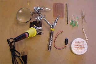
Figure 2 Soldering tools and supplies
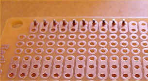
Figure 3 Pins in Place
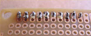
Figure 4 Pins
Soldered
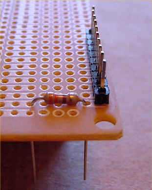
Figure 5 Resistor in
Place
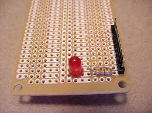
Figure 6
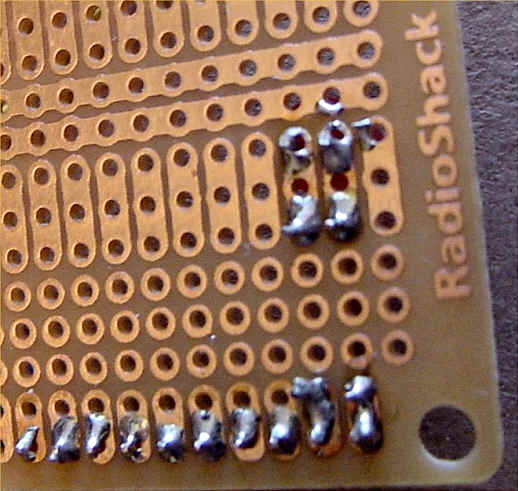
Figure 7
Finally, the most obvious warning:
The tip of a soldering iron is very hot.
Even momentary contact with the tip or other metal parts of the
iron will cause burns. Any
material that has a lower flash point than wood will catch fire instantly
when touched by the iron. Wood
will smolder, char, and eventually catch fire if the iron is held to it.
Always arrange your work area so that the iron's electric cord
cannot catch on anything. Have
an open box of baking soda nearby whenever you are working.
Baking soda makes a great fire extinguisher.
Just dump the soda on any 'thermal event' (i.e. fire) that occurs. The
soda can be brushed off and vacuumed up easily without hurting electronic
components.
Do not leave your iron plugged in if you are leaving your work
area.
Now,
for the practice circuit: Figure 2 shows
the components and tools you will be using.
Soldering iron, multipurpose holder, solder, rosin paste and
toothpicks, multipurpose PC board, header pins, resistors, LED's, and
fine sandpaper. The
multipurpose holder holds your iron when you are not using it and has a
wet sponge to wipe off the tip of your iron.
It also holds your PC board or components while soldering.
You can also use any odd little pieces of metal, ceramic, solid
wood, paper clips, or oven safe plastic to help hold your components in
the correct position while you work on them.
Condition
your iron as previously described. Adjust
the work holder so that the grips are just above your worktable.
Place the PC board into the clips with the copper side up.
Snap off a set of ten header pins from the header pin strip.
Put the short end of the pins through the PC board from the painted
side to the copper side as shown in Figure 3.
Note that the pins are in the outer set of holes.
Adjust the work holder to get the PC board to the right height, you
can get the pins to stand straight as shown in the figure.
You may need to find a book or block of wood to place under the
pins to get the right height.
Apply
a very thin layer of rosin paste to the part of the pin exposed above the
PC board and to the copper pads that surround the holes the pins are in.
Do not leave any lumps of rosin on the board and do not smear rosin
from one pad to the next. Remember
that the solder is going to flow wherever the rosin is spread.
Hold the iron and apply a small amount of solder to the tip.
Touch the tip to the intersection of the first pin and its PC board
pad. Some of the solder will
flow off the tip and onto the pad and the pin.
Touch the solder wire to the point where the iron is touching the
pad and pin if there does not appear to be enough solder on the joint.
Make sure not to cover the second hole in the pad with solder.
The tip should not be in contact with the pin and pad for more than
about two seconds at a time. Wipe
the tip of the iron on the sponge to remove any excess solder.
The plastic that holds the pins together is not very heat resistant
so once you have finished the first pin, go to pin six in the strip and
solder it. Continue to
alternate between pins (1,6,2,7,3,8,4,9,5,10) until you have all the pins
soldered as shown in Figure 4.
In the figure, pin six has an ideal solder joint.
The other joints shown are sloppy, but serviceable.
Turn
the board over and insert a resistor as shown in Figure
5. Since the resistor
has to stay in place when the board is turned back over, bend the leads
slightly outward so that they can not slide back through the hole.
Clip the leads to about the same length as the pins you just
soldered. Keep one of the
clipped leads to make the jumper. Put
rosin paste on the resistor leads and the pads around the holes that they
go through and solder them like you did the pins.
Turn
the board over again. Take one
of the leads you clipped from the resistor.
Bend it and insert it in the row next to the resistor as shown in Figure
6 to make a jumper. Turn
the board back over, apply rosin paste, and solder the jumper.
Turn
the board over once again. Insert
an LED as shown. Note that one
of the leads on the LED is longer than the other and that the lip around
the plastic part of the LED has a flat spot on the side with the long
lead. This is to indicate the
negative side of the LED. Put
the negative lead of the LED into the third hole of the pad where the
resistor is soldered and the positive end into the third hole of the pad
where the jumper is soldered as shown in Figure 6.
You know what happens next. Turn
the board over and solder the LED in place.
Make sure that there is a gap between the board and the bottom of
the plastic case of the LED large enough to allow you to insert a
multimeter probe. This will
make troubleshooting easier if you need to do it later.
When finished the bottom of the board will look something like Figure
7.
Congratulations, you have just
soldered your first electronic circuit.
Now you need to test it. Snap
a 9V battery onto the battery holder.
Make a small loop in the exposed part of the black insulated wire
and hook it around the pin next to the resistor.
Touch the exposed part of the red insulated wire to the pin next to
the jumper. If the LED lights
up, all of your solder joints in that circuit are serviceable.
Troubleshooting
If
the LED does not light up, you will need to troubleshoot the circuit.
Grab your multimeter. If
this is the first time that you have used the meter, very lightly sand the
surface of the probes. The probes on low cost meters get a small amount of
oxidation on them during shipping which will affect the meter's
accuracy. Set the meter to
read voltage. Remove the
battery pack from the circuit and touch the probes from the multimeter to
the leads from the battery. Your
meter should read around 9 Volts. If
it is reading less than 8 Volts, your battery is dead and needs to be
replaced.
If
the batteries are fine, check that you have the correct polarity, i.e.
that the negative battery lead is connected to the negative side of the
circuit. Test this by
switching around where the two battery leads are connected.
Note that while this is OK to do with this circuit, there are some
cases where reversing the polarity can harm sensitive components such as
microcontrollers in the circuit.
If
your polarity was correct, next you need to check the circuit path.
Switch the meter to read resistance.
Touch the one probe from the multimeter to the pin by the resistor
and the other probe to the pin by the jumper wire.
Most meters will read overload since most multimeters are not
strong enough current source to cause the LED to conduct electricity.
Surprisingly, a few cheap meters do produce enough current and
actually light the LED if the circuit is complete, however, if your
circuit was complete, the LED would have lit when the battery was
connected to it. Depending on
the meter you have the overload indicator may be different.
On some meters, OL is displayed.
On others, a 1 is displayed on the far-left side of the screen.
Still others flash a screen full of 9's.
Check the instruction that came with the meter to see which
overload indicator it utilizes. For
this article, we will use OL to indicate an over load reading.
If
the meter reads anything other than OL, there is a short circuit.
One of the solder joints on one side of your LED is touching
something in the circuit on the other side of the LED.
This allows the electricity to complete the circuit without going
through the LED. Turn the
board over and carefully look at each solder joint until you find one
where the solder connects two pads. Remove
some of the solder that bridges the pads by scraping it and then try to
power up the circuit again. If
it still doesn't light up, repeat the previous steps.
If
you get OL for the complete circuit, but no light you have an open
connection, probably a bad solder joint, somewhere in the circuit.
To isolate which solder joint is bad, you need to look at the
resistance through half of the circuit at a time. Set the multimeter to
resistance and put one probe of the multimeter on the pin closest to the
resistor. Put the other probe
on to the little bit of LED lead that you left between the plastic case of
the LED and the board. You
should be touching only the lead on the side of the LED connected to the
resistor. The meter should
read around 360 Ohms. If it
reads OL, the bad joint is somewhere between the first pin and the LED.
In that case, move the probe that was on the LED to the resistor
lead closest to the LED while keeping the other probe on the pin.
If you still see OL, the bad joint is neither the connection
between the LED and the pad nor the connection between the resistor and
the pad. In that case, move
the meter probe to
the other side of the resistor. If
you still get an OL reading, the bad joint is not on the pin side of the
resistor and either the solder joint for the pin or the joint for the
resistor lead on the pin side is bad.
Keeping one probe touching the pin, flip the board over and touch
the other to the copper pad on the board between the solder joints for the
pin and the resistor. If the
reading is still OL, the pin joint is bad.
What
you just did was eliminate one joint at a time from the "suspect
list". If the reading had
started at OL and then in one of the later steps had gone to the correct
reading (360 Ohms if the resistor was still in the part of the circuit
being tested or less than1 Ohm if the resistor was not in the part being
tested), the bad joint would have been the one that had just been taken
out the part of the circuit being tested.
If the meter does read around 360 ohms for the resistor side of the
circuit, repeat the process on the jumper side of the LED.
This time, you should get a reading of less than 1 ohm.
If instead, you get an OL reading, the bad joint is in that half of
the circuit. Isolate the joint
using the same steps described above.
If you identify a bad joint, put a very small amount of rosin paste
on the solder joint and reheat it with your iron until the solder once
again liquefies. Then remove
the iron, let the joint cool, and try the circuit again.
If you have a good battery and
get good readings on both halves of the circuit, but still no light, the
problem is in the LED. While
rare, you will at times get a pad part.
Go on to the next iteration of the circuit.
Conclusion
By the time you have made five
iterations of the circuit, you should be fairly comfortable with soldering
and bad joints should be rare. You
now have the basic tools and the basic skill needed to build a robot!
Next month, we will build a
complete robot. This robot
will be more than just a platform. It
will be mobile, sense its environment, change how it moves based on what
it senses, and be easily modifiable.
|
