 1
Sensor (The Edge Finder)- Only 1 sensor is needed to follow a
line. It actually follows one edge of the line,
continually sensing the transition from dark to light. Assuming a 2 motor
drive system, one motor is activated when the line is seen, the other is
activated when the line is not seen. This works fine at slower speeds but
becomes unusable as the bot goes faster -If the sensor crosses the other
side of the line, it will may head back in the opposite direction or if it
loses the line, it may spin in circles forever. The single sensor model is
seldom used with microcontrollers. Thinking in binary terms, the
sensor represents one of 2 possible states 1 or 0 (see the line or not see
the line). The only possible test conditions are:
0 - Off the line
1 - Over the line
 2
Sensors (The Line Avoider) - Using 2 sensors is similar to 1
sensor, except that a separate sensor controls
each motor. The sensors straddle the line and essentially try to avoid it.
This works better than 1 sensor but will wander off if it loses the line.
This happens because the bot cannot distinguish between straddling the
line and losing the line. If used with a microcontroller, you can
compensate somewhat through software. If you position the sensors close
enough together, you could follow actually follow the line instead of
avoiding it, but with only 3/4" typically to work within, this
can prove to be a challenge. The possible test conditions for this are:
00 - Straddling the line or lost the
line
01 - Found right side of line
10 - Found left side of line
11 - Not used unless sensors are placed less than the line's width apart
 3
Sensors (The Line Seer) - By adding a third sensor to the
previous design, you now make the bot cognizant of the line and it's
edges. The bot now take advantage if it's awareness of the line and deal
with situations like losing the line. It can also adapt more readily to
changing conditions like curves and straight aways in the track. It can
increase speed in the straight aways or adjust steering more subtly.
This is one of the more common sensor designs used, especially with
microcontrollers.
The possible test conditions are:
001 - Moving off the line to the left
010 - Centered over the line
011 - Slightly off the line to the left
100 - Moving off the line to the right
101 - Not used
110 - Slightly off the line to the right
111 - Not used (but could be used in the advanced or maze solving
contests)
5 Sensors (The Line Dancer)
- 3 sensors are obviously enough to follow a line efficiently, so why
would we want to add 2 more? The answer comes down to the bottom line of
the contest - speed. Adding 2 more sensors increases the resolution of
sensitivity that the sensors have of sensing the line's location. When a
bot is not moving too quickly, there is plenty of time for the bot to
adjust direction and speed to keep it on the line. What happens though
when the speed increases significantly? Instead of gracefully following
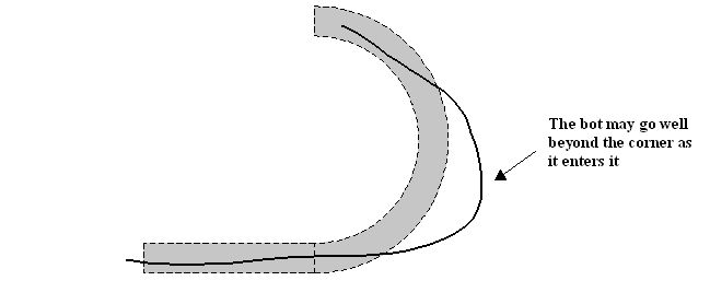
the line, you will see the bot begin oversteer and overshoot corners.

You can deal with overshoot/over-steer 2 different
ways:
- Reduce the speed until it is manageable
- Plan and compensate for
overshooting/over-steering
At some point, the speed of your bot will overcome
its ability to control itself. By acknowledging this will happen, you can
program your bot to correct for overshoot and be able to find the line
again.

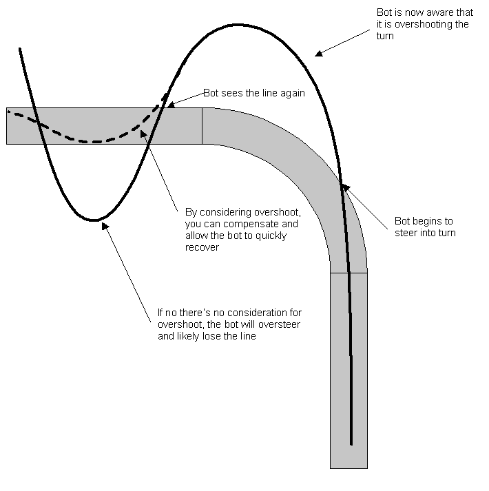
In the example pictured above, the bot
has lost the line as it entered the turn. Since it was beginning to turn
left as it entered, it knows to continue to turn left until it finds the
line. The far left sensor will find the line (at a rather acute angle)
before any other sensor. The normal logic for only the left sensor seeing
the line would be to steer hard left. But in this case, that would cause
us to cross the line, not turn into it. By recognizing the oversteer
condition, we can reverse the left only sensor logic to turn hard right
instead of left. This steers the bot back onto the track instead of across
it. This scenario is why the 2 additional sensors are important. They
provide for a finer level of control and quicker response to
overshoot/oversteer. Click here to see a
video of Arty overshooting the track and recovering.
As with the other designs, let's look at the
possible conditions with 5 sensors (I'll only list the useful ones):
00000 - Lost line from overshoot or break in line
00001 - Almost off the line, steer hard right and reduce speed
00011 - Near the right edge of the line, steer right
00010 - Right of the center of the line, steer right
00110 - Slightly to the right of the center of the line, slight
correction to the right
00100 - Centered over line, increase speed for straight runs
01100 - Slightly to the left of the center of the line, slight
correction to the left
01000 - Left of the center of the line, steer left
11000 - Near the left edge of the line, steer left
10000 - Almost off the line, steer hard left and reduce speed
11111 - Line intersection or circle at end of maze
As you can see, you have much finer control of the
bot's motion using 5 sensors. By looking at the sensors as binary numbers,
you can easily program the logic decisions.
-
Lineflag is a variable
that contains a binary representation of the 5 sensors
-
Servo(1) is the steering
servo PWM channel
-
Servo(2) is the drive
motors PWM channel controlled by an ESC
-
Overshoot is a flag that
indicates if we have lost the line at a turn
Bascom Basic Code Segment for Arty
Select Case Lineflag
Case &B00000 'No line
'If the bot loses the line, make steering changes
Servo(2) = Slow - Progspeed
If Lastlineflag < 4 Then
Overshoot = 1 'Overshot a righthand corner
Elseif Lastlineflag > 4 Then
Overshoot = 1 'Overshot a left hand corner
End If
Case &B00100 'Line under center sensor
Overshoot = 0
Servo(1) = Center
Servo(2) = Mediumfast - Progspeed
Case &B00110
Overshoot = 0
Servo(1) = Smallright
Servo(2) = Mediumfast - Progspeed
Case &B00010
Overshoot = 0 'Line under midright sensor
Servo(1) = Mediumright
Servo(2) = Mediumfast - Progspeed
Case &B00011 'Line between midright and right
sensor
If Overshoot = 0 Then
Servo(1) = Largeright
Servo(2) = Medium - Progspeed
Else
Servo(1) = Mediumright
Servo(2) = Medium - Progspeed
End If
Case &B00001 'Line under right sensor
If Overshoot = 0 Then
Servo(1) = Hardright
Servo(2) = Mediumslow - Progspeed
Else
Servo(1) = Largeright
Servo(2) = Mediumslow - Progspeed
End If
Case &B01100 'Line between center and midleft
sensor
Overshoot = 0
Servo(1) = Smallleft
Servo(2) = Mediumfast - Progspeed
Case &B01000 'Line under midleft sensor
Overshoot = 0
Servo(1) = Mediumleft
Servo(2) = Mediumfast - Progspeed
Case &B11000 'Line between midleft and left
sensor
If Overshoot = 0 Then
Servo(1) = Largeleft
Servo(2) = Medium - Progspeed
Else
Servo(1) = Center
Servo(2) = Medium - Progspeed
End If
Case &B10000 'Line under left sensor
If Overshoot = 0 Then
Servo(1) = Hardleft
Servo(2) = Mediumslow - Progspeed
Else
Servo(1) = Largeleft
Servo(2) = Mediumslow - Progspeed
End If
End Select