CIRCBot
Part 4: Serial, Servos and Sonar Continued
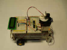
Power on your CIRCBot and plug the programming cable
into I45 - I49 on the
lower breadboard. The black wire should go into I49. Bring up the programmer in Bascom by clicking on
Program/Send to chip or pressing the F4 key.
The Programmer windows should pop up. Click the Auto
Program button to program the microcontroller. Next, click on the Lock
and Fuse Bits tab. This brings up the dialog box for changing fusebits
- Figure 2. Find Fusebit C and change it to 1:Divide Clock by 8
Disabled. The Write FS button will then be enabled. Click the
Write FS button to save the change. DO NOT
CHANGE ANYTHING ELSE AT THIS POINT! Changing other settings
in this dialog box can make the microcontroller non-responsive.
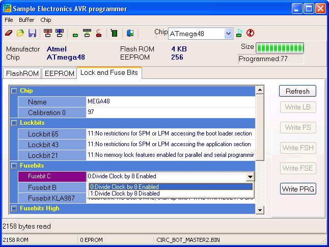
Figure 2 - Lock and Fuse Bits
The microcontroller and the program are now set to
8MHz and are ready for serial communications.
Repeat these steps for the secondary microcontroller
on the upper breadboard by plugging the programmer into I22 - I26
with the black wire going into I26. Both
microcontrollers must be set to 8MHz by changing the fuse bits for serial
communications to work properly.
Serial Communications in Bascom
To learn about serial communications, we are going
to load a small test program on each chip. The Mega48 on the lower level
will be referred to as the Primary MCU and the one on top will be
the Secondary MCU.
Click Here to download the serial test code -
serialtest.zip
Open the Secondary Serial
Test.BAS file in Bascom and compile it. Load the compiled program in to
the Secondary MCU on the upper level.
Open the Primary Serial Test.BAS file
in Bascom and compile it. Load the compiled progran in to the Primary MCU
on the lower level. Don't forget to move the programming cable!
If everything is connected properly,
the servo should rotate left, center and right and repeat and the LCD
display should display "DIST: xx" where xx is a number
between 0 and 255. That is the range of the detected objects at each
position.
Let's take a closer look at the test code.
|
