CIRCBot
Part 3: Sensors & Output
This project accompanies Part 3 of Servo Magazine's series,
Beginner's Robotics on $50 a Month. It covers building the IR
sensors, the bump sensors and installing the LCD display.
The first part of the article can be found in the February issue of Servo
Magazine.
The Part 3 kit is available here.
Click here for
the Bascom source code used for CircBot (zipped).
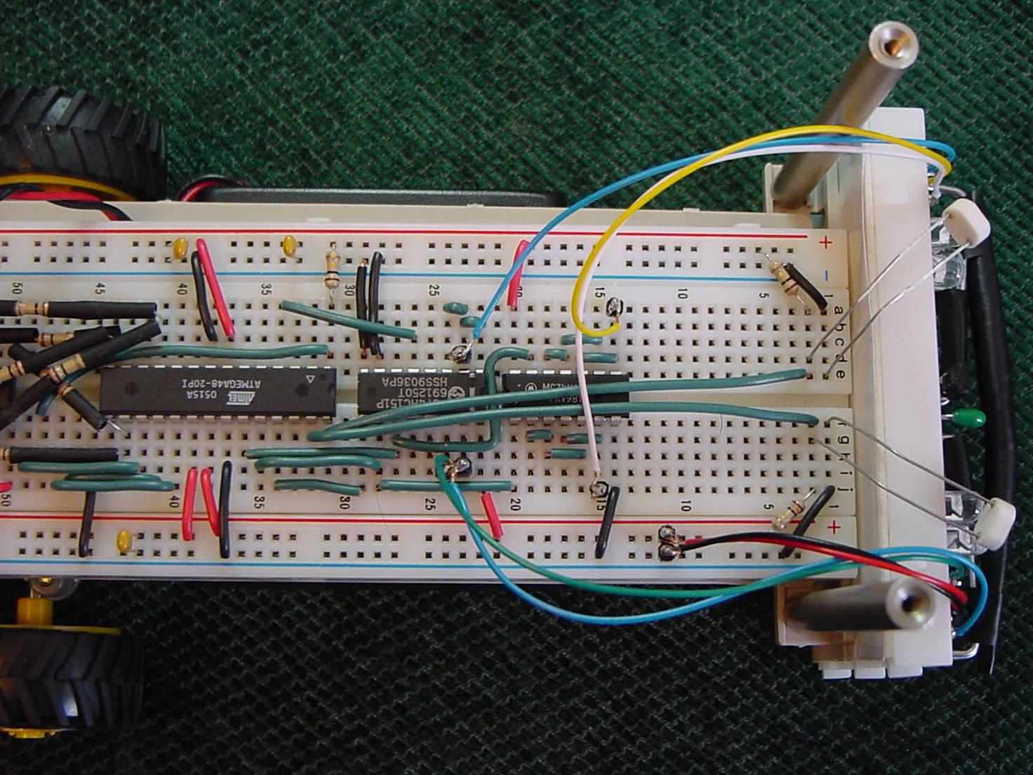
Main Board Connections
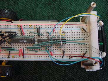
Click the image above to see a close up picture of
the main board wiring.
IR Obstacle
Sensor Circuit -
Part 2
IR test circuit that was
described in the magazine section of this article could be used as is for
a sensor. However, it would be
nice to get as much light out of the IR LED's as possible since that
would increase the range of the sensor.
The resistor used in the test circuit made sure that there was
enough load on the sensor's GL pin for the sensor to operate properly.
Replacing the resistor with two more IR LED's will keep the GL
pin loaded and will increase the amount of IR light.
Using the IR test circuit with three LED's would be sufficient
if all you wanted was to tell if there was something immediately in front
of the bot. However, it is
often useful to also be able to tell if the object in front of the bot is
more towards the left or right side of the bot.
For example, a sumo bot needs to turn toward an obstacle (i.e. the
opponent's sumo bot).
By
making two sets of IR lights and placing one set on each side of the
sensor, we can cause more light to be toward one side or the other of the
sensor's field of view by putting power to one set of lights or the
other.
You could use output pins form the microcontroller to power the
LED's. However, there is a limit to the amount of current a pin on the
microcontroller can source. Three
IR LED's will require more current than the microcontroller can provide.
If hooked directly to a microcontroller pin, they would cause the
power available to the rest of the chip to drop so low that the chip will
reset.
To get around this problem, we will use an inverter chip as a
buffer. The inverter will
limit the amount of current drawn from the microcontroller.
By running multiple inverters in parallel, we can increase the
amount of current available form the inverter to run the LED's.
The table in Figure 11 shows how to
wire a test circuit for the inverter.
Use the visible LED from the multiplexer test circuit to test the
output of the two-inverter chains. We'll
make the IR LED chains when we build the bump sensors in the next section.
|
Item
|
From
|
To
|
Notes
|
|
74HC04
Inverter Chip
|
F20
|
E15
|
Pin
1 @ F30 (chip faces backwards)
|
|
Wire
(GRN)
|
D14
|
D16
|
Length
5mm
|
|
Wire
(GRN)
|
C15
|
C17
|
Length
5mm
|
|
Wire
(GRN)
|
D17
|
D18
|
Length
3mm
|
|
Wire
(GRN)
|
G15
|
G17
|
Length
5mm
|
|
Wire
(GRN)
|
H16
|
H18
|
Length
5mm
|
|
Wire
(GRN)
|
G18
|
G19
|
Length
3mm
|
|
LED
|
A14
|
Upper
GND 14
|
Temporary,
remove after test
|
|
LED
|
J15
|
Lower
GND 15
|
Temporary,
remove after test
|
|
Test
Lead (RED)
|
Any
+V spot
|
Tester
board
|
Temporary,
remove after test
|
|
Test
Lead (BLK)
|
Any
GND spot
|
Tester
board
|
Temporary,
remove after test
|
|
Test
Lead (BLUE)
|
D19
|
Tester
board
|
Temporary,
remove after test
|
|
Test
Lead (GRN)
|
G20
|
Tester
board
|
Temporary,
remove after test
|
|
Wire
(GRN)
|
C19
|
G27
|
Length
30mm Install AFTER test
|
|
Wire
(GRN)
|
J20
|
J28
|
Length
20mm Install AFTER test
|
Figure
11 Inverter Wiring
The Bump Sensors
There will be objects that the
IR detector will not see. If a
material either absorbs IR or is transparent at IR frequencies, the IR
detector will not see it. Bump
sensors provide a method for your bot to sense these obstacles.
There are dozens of designs out there for making bump sensors.
They range from the simple to the complex.
On the simple end is a springy wire connected on one end to GND
with the other end terminating in mid-air just in front of a contact pad
which is wired to a terminal on the microcontroller (the terminal is also
connect to +5V through a 100 KW
resistor). When something
pushes the wire to contact the pad, the terminal on the microcontroller
goes from reading 5V to reading 0V. On
the complex end there are multi-lever linkages with molded parts that
surround a bot and activate different combinations of switches depending
on where contact is made.
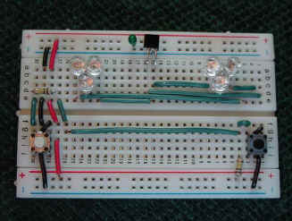
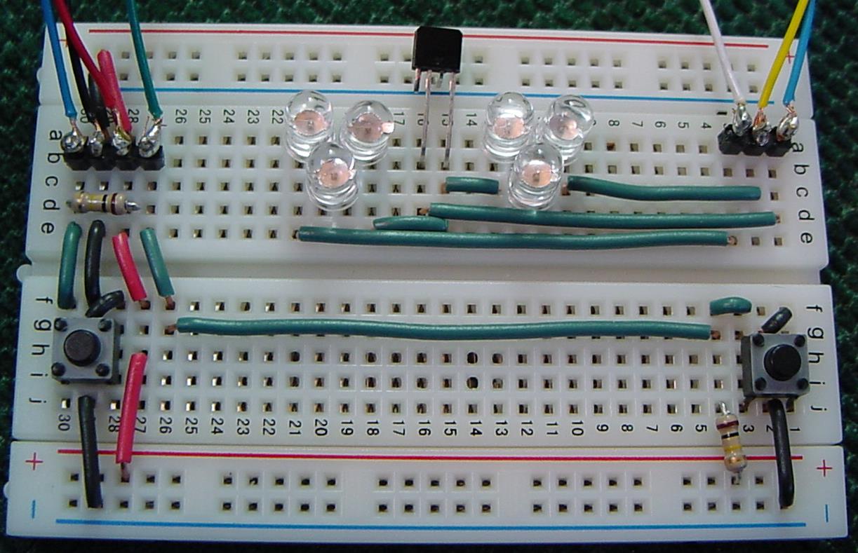
Figure 12
Front Breadboard
(Click to Image to View)
he bump sensors for this bot fall somewhere in between.
They use micro-switches which are pushed by a bumper made of
ceiling hanging wire and electrical tape.
It works, but with a little creativity, you should be able to come
up with better designs. Use
Google to search for bump sensor on the net for ideas.
We'll install the micro-switches and their circuitry first and
then make the actual bumpers. Figure
12 shows the small breadboard with the IR sensor, its LED chains,
and the bump switch circuitry. The
table in Figure 13 describes how assemble
the circuit in the previous figure.
|
Item
|
From
|
To
|
Notes
|
|
IR
LED
|
A5
|
A6
|
Neg
side at A6
|
|
IR
LED
|
A7
|
A8
|
Neg
side at A8
|
|
IR
LED
|
C6
|
C7
|
Neg
side at C7
|
|
IR
LED
|
A25
|
A24
|
Neg
side at A24
|
|
IR
LED
|
A23
|
A22
|
Neg
side at A22
|
|
IR
LED
|
C24
|
C23
|
Neg
side at C23
|
|
Small
Capacitor
|
Upper
+V 18
|
Upper
GND 18
|
|
|
IR
Sensor
|
See
|
Picture
|
GL
Pin 4 @ A15, Signal pin 2 @ A16
|
|
Wire
(GRN)
|
C15
|
C8
|
Length
17mm
|
|
Wire
(Grn)
|
D16
|
D1
|
Length
37mm
|
|
Wire
(GRN)
|
E15
|
E22
|
Length
17mm
|
|
Wire
(GRN)
|
E25
|
E3
|
Length
54mm
|
|
Wire
(GRN)
|
D5
|
D2
|
Length
7mm
|
|
Wire
(RED)
|
Upper
+V 28
|
A28
|
Length
10mm
|
|
Wire
(BLK)
|
Upper
GND 29
|
A29
|
Length
7mm
|
|
100
K resistor
|
D30
|
D28
|
Length
5mm
|
|
Wire
(GRN)
|
E30
|
F30
|
Length
7mm
|
|
Wire
(BLK)
|
E29
|
F29
|
Length
7mm
|
|
Wire
(RED)
|
E28
|
F27
|
Length
8mm
|
|
Wire
(GRN)
|
E27
|
F26
|
Length
8mm
|
|
Wire
(BLK)
|
F27
|
G26
|
Length
3mm
|
|
Wire
(BLK)
|
J29
|
Lower
GND 29
|
Length
10mm
|
|
Wire
(RED)
|
H27
|
Lower
+V 27
|
Length
12mm
|
|
Switch
|
G30
|
J28
|
Break
off center tab, face tab side to center
|
|
Wire
(GRN)
|
G26
|
G4
|
Length
54mm
|
|
Wire
(GRN)
|
F4
|
F3
|
Length
3mm
|
|
Wire
(BLK)
|
G2
|
F1
|
Length
4mm
|
|
Wire
(BLK)
|
Lower
GND 2
|
J2
|
Length
10mm
|
|
100
K Resistor
|
Lower
+V 4
|
J4
|
Length
7mm
|
|
Switch
|
G3
|
J1
|
Break
off center tab, face tab side to center
|
Figure
13 Front
Breadboard Wiring
You will need to make some jumper wires to connect the small
breadboard to the main board. Cut two 4-1/2 inch pieces from the six
stranded cable which was left over from building the programming cable in
last month's article. Slide
all of the wires out of the sleeves.
Cut one red and one black wire down to 2-1/2 inches.
Strip 9mm (about 1/4") off the ends of all the wires from one set
and off the ends of the blue wire from the other set.
Break off a set of four header pins from the strip of header pins.
Solder the wires to the pins in the following order: Blue, Black,
Red, Green. Break off another
set of three header pins. Solder
the following wires in order to these pins: White, Yellow, Blue.
Break off seven individual pins from the header strip.
Solder one to the other end of each wire you just attached to the
sets of pins.
Plug the set of three pins in to
the small breadboard in locations B1 through B3 with the blue wire in
position B1. Plug the set of
four pins in the locations B27 through B30 with the green wire in position
B27.
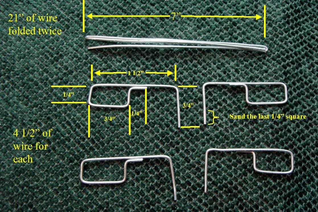
Now, we will bend the actual bumpers out of ceiling hanging wire.
The ceiling wire is fairly easy to bend into a desired shape using
pliers. It is also slightly
springy so it will return to its original shape after the bot backs away
from an object it has bumped. The
problem is keeping the ceiling wire bumper positioned over the
micro-switch so that it will press it when something makes contact with
the bumper. We will take
advantage of the fact that the breadboard holes are actually square.
The ceiling wire is 18 gauge, which is slightly larger than what
the holes can take. We will
sand an end of the wire square to fit the hole. This will keep the whole
piece form rotating.
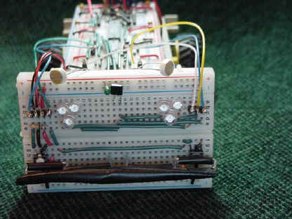
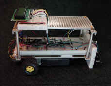
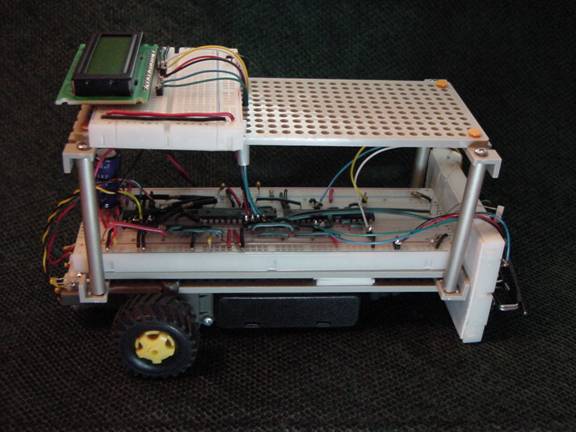
Figure 15
Completed Front Board
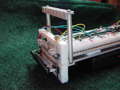
Figure 16 Standoffs for second level
However, the wire can still flex sideways.
To keep that from happening, we will double up the pieces and use
electrical tape to hold them together.
Figure 14 shows how to make the
individual pieces while Figure 15 shows
them assembled. Bending the
bumpers is a bit of an art. Take
your time bending the pieces. The doubled pieces have to match close
enough to be taped together
Attaching the Vertical
Breadboard
The flat of the angle piece on
the front of the CIRC Bot will be where the small breadboard will be
attached. Position the small
breadboard in front of the bot with the bottom of the board just above the
ground as shown in Figure 15.
On the back of the board, mark the area where the board is making
contact with the rest of the bot. Use
a knife to cut the wax paper which covers the double stick tape just the
area where the board will touch the rest of the bot.
Stick the board to the front of the bot.
Take the black and red jumper wires and attach them to convenient
locations on the lower +V (for the red) and GND (for the black) rails of
the main board. The blue wire
that is next to the black wire goes to I23, the green wire goes to I24,
the white wire goes to J15 and the yellow wire to A14.
Adding a Second Level to the CIRC Bot
We are quickly running out of
space on the CIRC Bot. To make
room for the LCD screen and for next month's parts, we need to add a
second level to the bot. Place
standoffs in the four outrigger holes as shown and attach two angles to
the top of the standoffs as shown in Figure 16.
Now use two-piece plastic rivets to attach a base plate to the top
of the angles. Take the logic
tester circuit apart and place its breadboard sideways on the top plate at
the back end of the bot with row one of the breadboard to the right when
looking from the back of the robot.
LCD Display Circuit
Header pins will need to be
installed in the fourteen holes along the top of the LCD.
Please refer to the datasheet for the LCD which can be found on the
Wright Hobbies website. NOTE
that there is some variation in the LCD's provided.
Some will have sixteen holes instead of fourteen.
You only need to add header pins to the first fourteen holes
starting at the hole closest to the edge (marked "1" on the
datasheet). Snap a strip of
fourteen pins from your header pins. Solder
the short end of the pins into the holes so that the long legs of the pins
are facing away from the LCD Screen.
The LCD will be installed on the second level so there will need to
be a number of wires run from the first level to the second.
Cut a 4-1/2 inch piece from the six stranded cable which was left
over from building the programming cable in last month's article.
Remove all but one inch of the outer sleeve.
Strip the ends of each wire. Break
off a set of four pins from the header strip.
Solder the following wires to those pin in this order: Red, Black,
Blue, Green. Break off another
two pins from the header strip. Solder
the remaining two wires, Yellow and White, to those pins.
Fish the unsoldered ends of the wires through the center hole in
the row of holes which is directly in front of the breadboard on the top
plate. Break off another set
of four pins and solder to them the other end wires which were soldered to
the other four pin strip. The
wires should be soldered in the same order: Red, Black, Blue, Green.
Finally, break off two single pins from the header strip.
Solder one of the pins to each of the remaining wires (Yellow &
White).
Wire up the LCD to the top breadboard as described in the table in Figure
17. Note that the
wiring table substitutes a small jumper for the potentiometer shown on the
schematic in the magazine portion of this article. In most cases, this
jumper will set the LCD contrast to the correct level.
However, if you wish to adjust the contrast, you can use the
potentiometer included in the kit. The
pins on the pot do not sit well in the breadboard so you will need to
solder a header pin to each of the pins on the pot if you decide to use
it.
|
Item
|
From
|
To
|
Notes
|
|
Wire
(BLK)
|
Front
GND 25
|
Main
Board (MB) Top GND 36
|
Length
65mm (twist with next wire)
|
|
Wire
(RED)
|
Front
+V 25
|
MB
Top +V 36
|
Length
65mm (twist with previous wire)
|
|
Jumper
(GRN)
|
MB
G33
|
F10
|
See
Text on Jumper Wires
|
|
Jumper
(BLU)
|
MB
G34
|
F11
|
See
Text on Jumper Wires
|
|
Jumper
(BLK)
|
MB
G35
|
F12
|
See
Text on Jumper Wires
|
|
Jumper
(RED)
|
MB
G36
|
F13
|
See
Text on Jumper Wires
|
|
Jumper
(YEL)
|
MB
C36
|
F18
|
See
Text on Jumper Wires
|
|
Jumper
(WHT)
|
MB
C35
|
F20
|
See
Text on Jumper Wires
|
|
Wire
(BLK)
|
Rear
GND 23
|
J23
|
Length
10mm
|
|
Wire
(BLK)
|
F23
|
F30
|
Length
17mm
|
|
Wire
(RED)
|
G22
|
G28
|
Length
15mm
|
|
Wire
(GRN)
|
G21
|
G29
|
Length
20mm
|
|
Wire
(BLK)
|
G19
|
G30
|
Length
27mm (add DOUBLE the normal stripped wire length)
|
|
Wire
(BLK)
|
Front
GND 1
|
Rear
GND 1
|
Length
45mm
|
|
Wire
(RED)
|
Front
+V 1
|
Rear
+V 1
|
Length
45mm
|
|
Wire
(Red)
|
Rear
+V 28
|
J28
|
Length
7mm (power to pot)
|
|
Wire
(BLK)
|
Rear
GND 30
|
J30
|
Length
10mm (GND for pot)
|
|
Wire
(GRN)
|
I28
|
I30
|
Length
3mm (substitute for pot)
|
|
LCD
|
H23
|
H8
(16 pin)
|
Pin 1 @ H23
|
Completed Top Level
Programming
As
with last month's article, sample code to test your new hardware can be
found both on the SERVO website and at http://www.wrighthobbies.net/guides/.
This month's program utilizes a timer interrupt.
A timer interrupt causes the program which it is in to stop what it
is doing and go do what is called out in the interrupt service routine
(ISR). Once the ISR is
completed, the program is returned to what it was doing before it was
interrupted.
You can use ISR's two ways. One
way is to put high priority actions in the ISR to make sure that they run
no matter what the rest of your program is doing.
For example, we could have put the sensor read routine and the
motor control case routine in the ISR.
This would have made sure that the sensors are read and their
information is acted upon at a regular interval.
The problem with that is that the length of time spent in the ISR
would be so long that it would be time to call the ISR again as soon as
the routing has ended.
This program uses a different approach where a low priority action
can only occur after the ISR has been called a certain number of times.
Inside the ISR is a counter that increments each time the ISR is
called. In the main program is
an IF statement that is true only after the counter has exceeded a certain
value. The true part of the IF
statement resets the counter and sends data to the LCD.
The rest of the main program is short and executes fairly fast when
the LCD is not called. In
fact, it executes so fast the LCD could not keep up if data was sent to it
each time the microcontroller cycled through main loop of the program.
The interrupt counter and the IF statement keeps the LCD refresh
rate down to an acceptable level and help speed up the rest of the main
code.
Variations
The
IR detector presented was about as minimalist as you can get.
Taking a look at the data sheet for the IS471F (http://www.junun.org/MarkIII/datasheets/IS471F.pdf),
we can see that there are a lot of different subsystems included in the
tiny sensor. David Cook's
Robot Room website has a page about building a modulated IR receiver out
of component parts http://www.robotroom.com/Infrared555.html
and another about building a transmitter http://www.robotroom.com/InfraredTransmitter.html.
Building these two circuits will give you a much better
understanding of what the IS471F is doing.
Sharp also makes the GP family of IR distance sensors which are very
popular in hobby robotics. Take
a look at http://www.acroname.com/robotics/info/articles/sharp/sharp.html
for a discussion of these sensors, how they work and how to interface them
to a microcontroller.
Pointing the IR sensor out from the robot makes it an object
detector. Pointing it down
makes it either a line follower or an edge detector.
Like with visible light, different materials reflect different
amounts of IR light. Most (but
not all) brands of black electrical tape reflect very little IR light
while white paper, white fiberboard, and Melamine all are highly
reflective in IR. This allows
a line follower to be built using one or more IR detectors.
For more information on line following, look at the article
"Line Following - A Guide to Using Sensors" in the guides'
section of the Wright Hobbies website.
When you using an IR detector facing forward as an obstacle sensor,
you want the bot to stop and turn when the sensor detects an object. When
you use it facing downward as an edge detector, you want the bot to stop
and turn when the sensor doesn't detect an object (i.e. the floor under
it). This is harder than it sounds since a single sensor in the front of
the bot near the centerline will only detect if the center of the front of
the bot is over the edge. It
wells you nothing about whether an edge is near the wheels.
I advise using a short table with pillows around it and a friend
standing on the other side of the table ready to catch the bot when you
try out your edge detection design.
IR transmitter / receiver pairs are also used to make wheel
encoders. The Seattle Robotics
Society has a good article on building an IR wheel encoder and using it
for "dead reckoning" or a robot's position on their website at http://www.seattlerobotics.org/encoder/200010/dead_reckoning_article.html.
There is a lot more to the bump switch.
Chris and Dawn Schur's bumper logic web page, http://www.schursastrophotography.com/robotics/bumperlogic.html,
goes into the benefits of a well thought out bumper design.
The micro-switches used in the bump sensors can also be used
as input devices. You can
modify the BASCOM program to display a menu on the LCD screen.
Use the left bump switch to go up the menu and the right switch to
go down. Add two more buttons
for enter and escape and you can create an interactive system on your bot.
Having such a system, you can create a program that allows the bot
to do different things based on what has been selected on the menu.
While the multiplexer chip does have a few ports left, you
will once again run out of usable ports if you try to do multiple ideas
from this section at one time. However,
if you look at the datasheet for the 74HC151, you will notice that there
is also a 16 to 1 version, the 74HC150. This chip will allow you to try
several of the variations suggested here.
It will require one more port on the microcontroller.
Do not use pins 2 or 3 (PD0 or PD1) on the microcontroller since
they will be needed next month. However,
pins 9 & 10 are also still available.
Conclusion
Your CIRC Bot is becoming more
complex. Last month, it had
the hardware necessary to seek or avoid light - based on how you
programmed it. This month, it
can also know when it has hit or is about to hit an obstacle.
If you strike out on your own and try some of the variations, it
can also be made capable of line following, edge detection, or dead
reckoning its position. By
mixing and matching the bits you have built on your CIRC bot and creating
the right code, you can make a bot that can do maze solving, sumo
wrestling, object retrieval, or line following.
Next month, you will learn how to free your bot of the limitations
of a single small microcontroller and give it the gift of "sight" with
scanning sonar.
|