Bascom requires a
programming cable to interface with AVR microcontrollers. Getting
the cable installed and configured properly can be a bit of a
challenge. This guide will walk you through the steps required to
connect and configure the Sample Electronics programmer to work with
Bascom.
Step 1 - Building the Sample Electronics
Programming Cable
The Sample Electronics Programming cable is
part of the CIRCBot Part 2 kit and the Chibot's Tabletop Kit. Please
refer to the instructions included in these kits to build the cable.
The cable schematic is in Bascom's help file or you can view it
here:
Sample
Electronics Programming Cable Schematic
After building the cable, use the schematic to
double check the connections. Note - The
pinouts on the 5-pin connector are not the same for the CIRCBot and
the Tabletop Bot. Be sure to verify the pinouts based on the
documentation for the kit you are builiding.
Once the cable is built, plug it into the
parallel port on your computer. If you computer does not have a
parallel port, you will need to add one. Look for a PCI card
with at least one ECP/EPP parallel port. A USB to Parallel
adapter will not work!
Step 2 - The Parallel Port
For the Sample Electronics programming cable
to work, the parallel port must be configured for ECP or EPP
mode and you will need to know the address it uses. You should be
able to tell what mode it is in by checking the Parallel Port in
Device Manager. To access Device Manager, go to Control Panel, and
click on System. In the System Dialog Box, select the Hardware tab
then click on Device Manager. You should see a window like this:
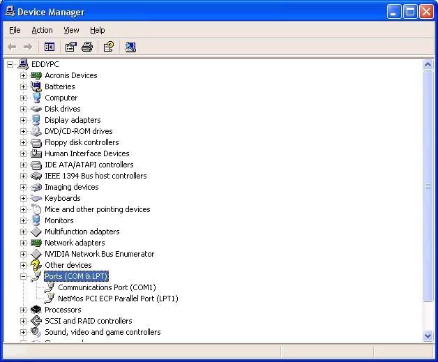
Look for the Port (COM & LPT)
section and expand it. You should see a Parallel port list similar to
the one in the image above. Notice that the parallel port is listed as
ECP. You may need to use your PC's BIOS configuration menu to change
the parallel port to ECP or EPP mode. Please refer to your PC's
documentation on how to configure BIOS.
Double click on the parallel port
to bring up the Properties window. Click the Resources tab. You should
see something like this:
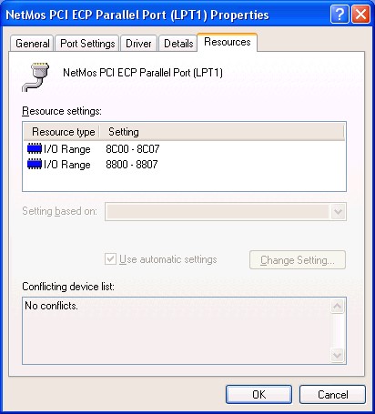
The I/O Range tells us the address
used by the parallel port. We need this information for Bascom.
The address is typically 378, 278 or 3BC but since my parallel port
was an add-in card, the address is 8C00. Write down the address for
Bascom in the next step.
You can close the Device Manager
windows and launch Bascom.
Step 3 - Setting up Bascom
After launching Bascom, click on
Options, Programmer. You should see a dialog box like this:
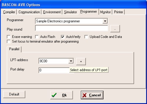
Select Sample Electronics
programmer from the Programmer list. Next, select the LPT-address
that matched the one you wrote down. If your address is not on the
list, click the button with the + sign and type in your address. Click
Save then select the new address from the list. Click Ok and you
should now be able to use the Sample Electronics programming cable
with Bascom.
Still Need Help?
Stop by our forums and let us know.
We will be happy to assist you!
http://www.wrighthobbies.net/phpBB2/index.php
|
